
A lot of people have asked me about how to add resistors in for anyone who wants to swap out their tail light bulbs to LEDs and prevent the hyper flashing. So I've created this thread for people to reference.
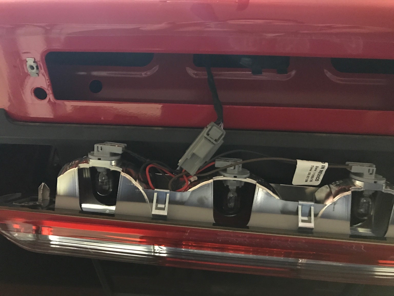
To start, the full set of rear lights are all wired in parallel. So if you open up the wire loom before all of the bulbs, you'll see 4 colored wires:
Black - common negative
Gray - turn signal positive
Orange - tail light positive
Yellow - reverse positive
Using this MS-Paint diagram, you can see that the common ground wire comes out from the truck (big blue block on the left) to the first bulb, comes out of that bulb to the middle bulb, out of the middle to the last.
***NOTE*** The left bulb in the diagram is actually your bottom bulb in the tail light housing
![Image]()
So as you can see here, this is before all of the bulbs, you T-Tap/Splice the resistor to the black wire and the gray wire:
![Image]()
You do the same for the last bulb:
![Image]()
Here is a full picture showing everything.
![Image]()
Any questions???
To start, the full set of rear lights are all wired in parallel. So if you open up the wire loom before all of the bulbs, you'll see 4 colored wires:
Black - common negative
Gray - turn signal positive
Orange - tail light positive
Yellow - reverse positive
Using this MS-Paint diagram, you can see that the common ground wire comes out from the truck (big blue block on the left) to the first bulb, comes out of that bulb to the middle bulb, out of the middle to the last.
***NOTE*** The left bulb in the diagram is actually your bottom bulb in the tail light housing

So as you can see here, this is before all of the bulbs, you T-Tap/Splice the resistor to the black wire and the gray wire:

You do the same for the last bulb:

Here is a full picture showing everything.

Any questions???
")