Chevy Colorado & GMC Canyon banner
41 - 60 of 115 Posts
Well, at least one of my resistors lasted just 13 days. Luckily I had a spare pair (I had bought a set for my switchbacks up front, then decided to splurge on the running-lights harness). I'm assuming it was a resistor, anyway -- the problem was intermittent but when I removed those infernal t-taps the connections looked solid, clean cuts through the insulators at all points.

While fiddling with the new t-taps, I wondered -- any reason the resistors couldn't be installed in series instead of in parallel with t-taps? I'm guessing the resistance of the LED (the other branch of the parallel circuit) is so low that it's probably irrelevant to the overall resistance. It would be nice to use a plug connector instead of those awful taps.

That also got me wondering, what happens if you install an incandescent bulb with the resistors in place? I was planning to keep my old bulbs as emergency backups.
 
I just installed rear LED's following this thread, works perfect. 2 resisters for each tail light assembly, 1 for each bulb.
 
With the pictures not working, I could use a little guidance.

I was able to install resistors on the top bulb with no issues, as there is only 1 grey and 1 black wire.

However, on the bottom bulb there are 2 grey and 2 black wires (I assume turn signal (+) in and out and ground (-) in and out). On the bottom bulb, does it matter which grey wire I tap for resistor and which black wire I tap (in the absence of the diagram)? If so, could someone describe which wire I should tap (outside-grey or inside-black)...something like that to give me just a little direction please?
You want to tap the gray and black "in" wires, since the "out" wires go to the other light.

Tagging @Blue15ColoradoLT to maybe fix the PhotoBucket-hostage pix...
 
Discussion starter · #47 ·
With the pictures not working, I could use a little guidance.

I was able to install resistors on the top bulb with no issues, as there is only 1 grey and 1 black wire.

However, on the bottom bulb there are 2 grey and 2 black wires (I assume turn signal (+) in and out and ground (-) in and out). On the bottom bulb, does it matter which grey wire I tap for resistor and which black wire I tap (in the absence of the diagram)? If so, could someone describe which wire I should tap (outside-grey or inside-black)...something like that to give me just a little direction please?
Until I can find the time to move all my pictures from Photobucket else where, the best way is to use split the wires to their appropriate destination. Start at the bulb, one black wire and one gray wire goes to the truck, the other black and gray wire go to the top bulb. Then put one resistor on the set towards the truck.
 

Attachments

Ok, I'm not a big LED fan when it comes to having to add load resistors. With that being said, can someone chime in on adding a load resistor closer to the BCM? I guess what I'm asking is, can you add a resistor closer to the BCM so it could be a higher value to lower the load on the circuit? I'm thinking the wire size is pretty small so it would help in lowering the power consumption on the circuit. I bet if you were good enough with math and ohms law you could have LEDs and a lower amp draw. Maybe this is too much trouble?
 
A few questions and comments:

7444/7443 bulbs are 25/27 Watts in the higher power filament aren't they?
6 Ohm resistors will dissipate 33.84 Watt at 14.25 Volt. The LED doesn't pull much but it will add something.
All you really need to pull is enough to exceed the test requirement which takes a degraded but functional filament into consideration.

My second point is that aluminum housed power resistors depend on an external heatsink to achieve their power ratings. According to Vishay a 30 Watt RER75 needs to be bolted to a 5"x7"x2" .040" thick aluminum chassis to meet it's power rating - and then only up to 25C environment. You could try mounting them to the inside of your body panel with thermally conductive epoxy - but there is a chance you will brown your paint.
Power ratings generally decrease to 30% without heatsinks.
No wonder they fail...

If you feel experimental you might want to try 14 or 15 Ohm in a 50 Watt package. That *might* draw enough to avoid an open bulb warning and the maximum ambient in this area *might* be low enough to allow the resistors to live.
Don't mount them to any plastic you aren't willing to melt. You might get lucky. Don't we all like getting lucky?

Buy resistors at Digi-Key or Mouser vs. specialty lighting shops.

I think LEDs are great in systems originally designed for them. In this application I just don't see the factory incandescent's slowing me down or costing me mileage or reliability.

I'm running H9's up front FWIW.
 
You folks need to understand somethings about tapping into wires, especially outside to cab. T-taps are not water resistant, let alone water proof, and the wires will corrode especially if you live in a northern state that uses salt in the winter. Soldering is always a better solution, but again, you need to make the connection waterproof if at all possible. Heat shrink tubing is a good start, especially for protection against chaffing, but it's not water proof either. The best solution I've found has been liquid tape, and I use two coats to make sure everything is sealed tight. I used to use silicone, but under certain conditions, even it can leak. I've been using the liquid tape for several years, and it seems to be the best solution. Use the T-taps if you must, but coat the hell out of them afterwards. Your wiring will thank you.
 
To add a little note here . You do not have to work at the back of the car . Tail light harness can be disconnected behind the bumper.
Image
Image


Sent from my SM-G920V using Tapatalk
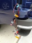
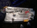
Two more pic.Can somebody tell me what the wires for under the resistor?
They are only on the driver side
Image
Image


Sent from my SM-G920V using Tapatalk
 
Could someone perhaps explain why I might be experiencing this?

I only have LEDs on the front turn signals. Now, for the past 4 vehicles I've done this with, I've only used LED on the front turn signals but I attached the resistors on the wiring near the rear lights, and all worked just fine. Now, for ??? reason, on this truck when I do that, it still wants to hyperflash. I'm at a loss here on this one.
 
I understand some people love to do the install themselves but this is a nice plug and play option.
https://www.youtube.com/watch?v=3L5xaG7xwyU&t=6s
I was looking at that harness but it only uses 1 resistor per side for two bulbs. I thought you needed 1 resistor per bulb, as mentioned above, which would be 2 per side. Have you had any issues with your rear tail lamps with only having one resistor per side?
 
41 - 60 of 115 Posts